
How it works
How are the contour lines depth-tested?
Why the contour lines don't need a depth offset. They're worked out in the terrain's own pixel shader, so the only depth test they go through is the ground's.
Project: OPFRAME · Oct 2026
The short answer is that the contour lines never make a depth decision of their own, so there’s nothing to offset.
A contour line isn’t a separate thing drawn on top of the terrain. When the terrain’s pixel shader colours a bit of ground, it also checks whether that pixel is on a contour, and if it is, it mixes the contour’s colour into the ground’s. The only depth test is the one the ground goes through anyway, once per pixel, while the terrain mesh is being drawn. A line is always exactly as visible as the ground underneath it.
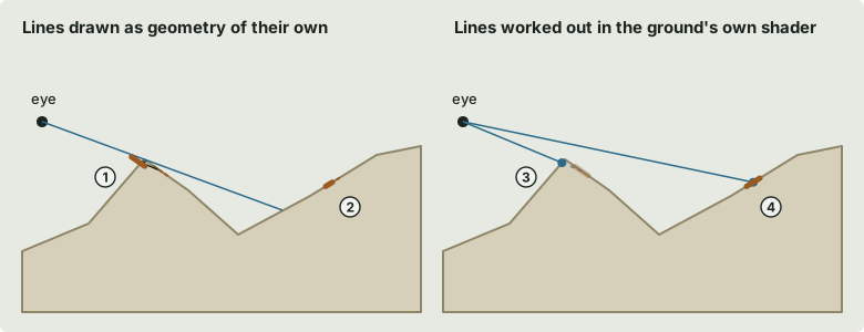
The diagram compares drawing the lines as separate geometry with doing it in the shader:
- Draw them as geometry with an offset, and a line just behind a ridge gets pulled towards the camera and can show through the ridge.
- Leave the offset out, and the line and the ground beneath it are at the same depth and fight over the pixel. The line flickers (z-fighting).
- Do it in the shader, as OPFRAME does, and the pixel in front of a hidden contour belongs to the nearer slope. That slope wins the depth test, so the contour behind it never even gets shaded.
- A visible contour is just colour on the ground you can see, so it shows up exactly where that ground is.
The depth test itself
Depth is kept as one 32-bit float per pixel. It’s stored “reversed”, with near at 1 and far at 0, and there’s no far limit, which keeps the precision good at long range. The nearer ground wins and its depth gets written.
There’s no depth bias (Direct3D’s version of polygon offset) anywhere in the renderer.
The shader also never changes a pixel’s depth and never throws a pixel away. Because of that, the GPU is free to run the depth test before the shader, and ground hidden behind nearer ground is never shaded at all. It doesn’t get the chance to have a line on it.
How the shader decides a pixel is on a line
For every ground pixel that passes the depth test, the shader goes through the same few steps.
First it reads the ground’s height above mean sea level at that pixel, h, from the same height map
the vertex shader uses to shape the mesh.
Next it needs to know how quickly that height changes across the screen. GPUs shade pixels in 2 × 2
blocks, so a shader can ask how much any value differs from the pixel next to it (ddx) and the one
below it (ddy). Taken together, dh = length(ddx(h), ddy(h)) is how many metres of height a single
screen pixel covers at that spot. It’s large on steep or distant ground and small on gentle ground
close by.
Then it works out how far the pixel is from the nearest contour level, in metres of height:
d = |h − round(h ÷ interval) × interval|.
Dividing by dh turns that into pixels, so d ÷ dh is how many pixels this one is from the line.
Setting the cover from that gives a line with a fixed width on screen, whatever the slope or the
distance.
Last of all, it deals with crowding. Where the contour levels would come closer than about 2.5 pixels
apart, the lines fade out, and they’re back at full strength by 6 pixels apart. Without that, steep
ground would turn into a solid brown smear. Ground that doesn’t change at all (dh close to 0), like
the sea at 0 m, gets no line even when it sits exactly on a level.
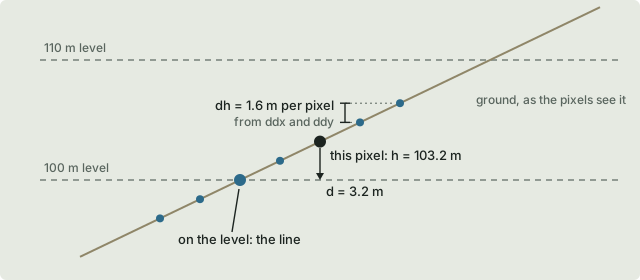
To take an example, with a 10 m interval a pixel at 103.2 m is 3.2 m above the nearest level. If one pixel spans 1.6 m of height at that point, it’s 3.2 ÷ 1.6 = 2 pixels from the line, and a 1-pixel line won’t reach it. Two pixels further down the slope is the one sitting on the 100 m level, and that one is drawn in full.
Turning distance into cover
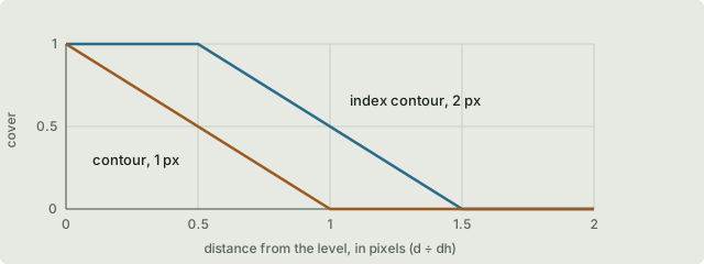
Cover is how much of the pixel the line takes up, from 0 to 1. It’s full within half the line’s width of the level, then drops away to nothing over one more pixel, which anti-aliases the edges:
cover = clamp(width ÷ 2 + 0.5 − d ÷ dh, 0, 1)Ordinary contours are 1 pixel wide, and every fifth one, the index contour, is 2 pixels wide. Both are multiplied by the display scaling, so they look the same on a high-DPI screen.
Lit and unlit lines
The ordinary contours are mixed into the map imagery’s colour before the ground is lit. That way they’re shaded by the hills and fade into the haze with distance, the same as the ground does. They’re drawn in a cartographic brown at 85% opacity.
The animated contour “pulses” are different. They’re mixed in after lighting and aren’t lit at all, like the range rings, so they look the same by day or by night. Both still happen in the same shader, after the same single depth test.
Why there’s no offset
You only need a depth bias when two surfaces at almost the same depth are competing in the depth buffer, as a line laid on the ground would be. Here there’s only one surface, so there’s nothing for it to compete with. A line can’t show through a ridge that hides its ground, and the ground it’s on can’t hide it.
Where along the ground a line sits
There is one subtlety. Each terrain tile’s height map is 256 × 256 texels and its mesh is a 64 × 64 grid of squares, so there’s a vertex every 4 texels. None of the texels actually becomes a vertex, though. Each vertex sits on the corner where four texels meet, and the vertex shader interpolates the height map there, so the vertex’s height is the average of those four. (At the edge of a tile it’s just the edge texel’s own value.) That means the mesh is shaped by only a quarter of the texels. The rest fall between the vertices and never reach it, and each triangle is flat between its corners.
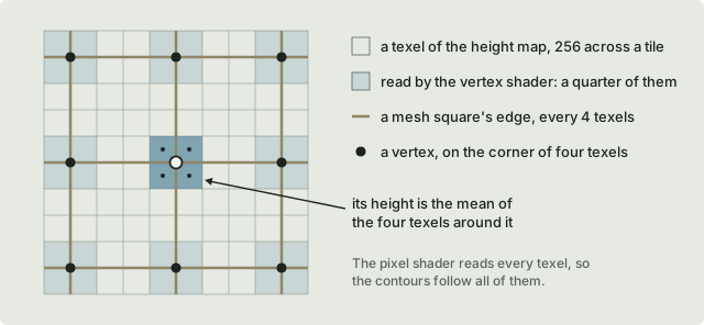
The pixel shader, on the other hand, reads the height map at every pixel, interpolated between the texel centres. It sees every texel, so its idea of the height is smoother than the flat triangles. A line ends up where the smooth height crosses the level, which can be a fraction of a square away from where the flat triangle would cross it. The line moves slightly along the ground, but it can never end up in front of or behind the surface, because it’s still only colour on the triangle that was drawn.
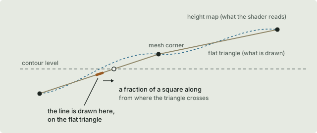
So the shift is sideways, along the surface, and the line’s depth is always that of the triangle it’s drawn on.
Looked at the other way round, the line is where the data says it is on the map. What’s approximate is the height of the triangle underneath it. In the 2D view the terrain is laid flat, so there’s no triangle height to get wrong and no shift at all; each contour is exactly where the height map crosses the level. In 3D, tiles are refined until a texel covers about a pixel at the nearest point of each tile, so a mesh square is never more than about 4 pixels across, and a line moves by a fraction of that whether it’s near or far. On distant, coarser tiles the shift is bigger in metres, but not on screen. The only time it grows is for a moment while a tile is drawn from its parent’s mesh, until its own has loaded.